As announced in our issue of the 12th inst., the Isle of Man Tramways and Electric Power Co. have recently put into operation a water power plant in connection with their Douglas-Laxey and Ramsey electric lines; and the successful results obtained have enabled them to shut down their steam plant entirely, the entire line, 1.8 miles in length, being worked solely by water power. The line in the summer time is used for tourist traffic, when the load on the several power stations reaches about 2,200 H.P., but for about seven months each year the line is dependent on the local passenger and freight traffic, which is comparatively light. The water power scheme, which was originated by Mr. Alexander Bruce, J.P., the chairman of the company, was designed by Mr. J. Shaw, A.M.I.E.E., the general manager and engineer, to work the line during these seven months, when the traffic is considerably reduced, and when it is necessary as far as possible to keep down the expenditure. As all the coal used by the company has to be imported from South Wales, the financial saving will be considerable.
PLAIN AND ELEVATIONS OF WATER POWER STATION ON LAXEY RIVER.
The Laxey river, which is seven miles from the Douglas and 11 miles from the Ramsey termini, has been utilised for obtaining the requisite power. The water has been taken after it leaves the "washing floors" of the Great Laxey Lead Mines, and the tail water is discharged direct into Laxey harbour, the total fall being 41ft., which, after deducting pipe losses, &c., allows a working fall of 38ft. As part of the water is used for ore-washing purposes at the Snaefell and Great Laxey Mines, it contains an immense quantity of sand, and special precautions have been taken to prevent this from reaching the turbines. The head work consists of a concrete weir 40ft. long by 4ft. 6in. high, built across the river.
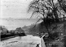 View above weir showing top water intake |
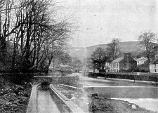 View of Laxey River at discharge from Tail Water canal |
At one end of the weir are two masonry archways 5ft. wide by 5ft. high, each fitted with a sluice gate and the necessary gear for raising and lowering the gates. The two gates are separated from the river by means of an iron grating 55ft. long by 5ft. 6in. high. During floods a large amount of debris is washed down the river, and the gratings protect the gates from being blocked. Inside the gratings is a large settling tank for the sand, the tank being emptied by opening the gate nearest the weir, which is used as a bye-pass for flushing purposes. The other gate is at the commencement of the head race, which consists of 826ft. of trench 5ft. wide, followed by 474ft. of trench 3ft. 6in, wide, the depth of each being 4ft. 6in. The first of these two sections was made larger in area, to allow the water to travel slowly and settle any sand which might have passed through the first settling tank. At the end of the larger section of race another settling tank has been formed by dropping the bottom of the trench 6in. for a distance of 50ft., and providing it with a 12in. flushing valve. At the end of the second section of race is built a masonry head box 8ft. by 11ft by7ft. 9in. deep, from which the water is conveyed to the turbines by means of 820ft. of steel pipes 3ft. diameter, The head box has also been built to act as a settling tank, thus preventing any sand from entering the pipes. An overflow weir 20ft. long has been built about half way along the race, the surplus water being conducted to the river through an underground conduit. Owing to the bad nature of the ground, the whole of the head race has been constructed of concrete, with the exception of one short length built of masonry. The pipe line, which had to be kept several feet above the ground, is supported on masonry piers. The pipes are made up of 1/8in. steel plates with double-riveted seams, and are fixed in 15ft. lengths. The joints are made with Kimberley collars run in with lead and well caulked. The tail race is 624ft. in length, 10ft. wide, and 13ft. 3in. below the floor of the turbine house, and terminates in Laxey harbour. The turbine house is 1,100ft. away from one of the company's steam power stations, and is a stone building 30ft. long by l 5ft. wide by 12ft. high. The fall from the level of the weir to the centre of the turbines is 26ft., the remaining 15ft. fall being obtained by means of draft tubes. The turbines are of the " Victor" horizontal type, and consist of two in dependent 12in. turbines in one casing with the shafts direct coupled ; so that, when there is only a small amount of water available, one turbine will be used, thus enabling the plant to be worked at its best efficiency. The turbines will develop 140 H-P., at a speed of 720 revs. per min.
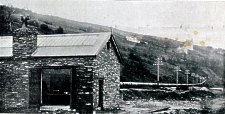 Exterior of Water Power Station and Pipe Line |
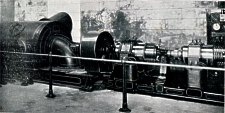 Interior of Water Power Station |
The electric generating plant consists of a combined bipolar dynamo and booster, the generator having an output of 160 amperes at 520 volts and the booster 160 amperes at from 100 to 200 volts. The generator and booster are coupled to the turbine by means of a friction clutch, which permits of the plant being used as an ordinary motor-driven booster in the summer time when the river is very low. The turbines, generator, and booster are provided with self-lubricating bearings, and are capable of maintaining long continuous runs without heating. The mains from the generator and booster and the regulating wires are carried overhead to the steam power station previously referred to, from which the turbine plant is entirely controlled. Two Lundell Ľ-H.P. motors, driven from a small storage battery, are used for opening and closing the turbine regulators. The switch panels for the generator and booster are attached to the main switchboard in the steam station. They comprise one generator panel, together with automatic switch, ammeter, voltmeter, positive and negative switches, shunt regulating switch, starting switch, and resist ance to work the generator as a motor for driving the booster when the water is low, and a recording wattmeter. The booster panel contains switches for controlling a motor driven booster in the steam station, and also the switches for controlling the turbine booster-viz., positive and negative switches, voltmeter, ammeter, shunt regulating switch, recording wattmeter, and change-over switches to connect either the turbine booster or motor booster to any of three feeders. Adjoining the generator panel is a small panel for controlling in either direction the two 4 H.P. motors for regulating the turbines. A small pipe has been carried from the head race, and is attached to a gauge glass fixed in a prominent position near the switchboard, so that the attendant can see the height of the water in the head race.
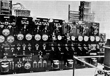
Switchboard at Water Power Station
The turbine plant is worked in connection with three battery sub-stations, each containing 250 cells of the Chloride " R " type, one at Laxey, at the foot of the Snaefell mountain railway, and the other two about five miles on each side, all three stations being worked in parallel. When the cars are taking current the turbine generator is assisting the batteries, but when the cars are descending the grades or standing the generator is charging the batteries. During the night time, when the cars are not running, the booster is connected in series with the generator, and the batteries are in turn charged at a heavy rate and at a high voltage through the underground feeders. This enables a full load to be maintained con tinuously on the turbines. The Isle of Man Tramways and Electric Power Co. were the first in the United Kingdom to use storage battery sub-stations for traction purposes, and they find these have proved exceedingly useful for working a long line with a minimum amount of steam plant.
The turbine plant described above has just completed a 240 hours continuous test, during which it maintained a steady load varying from 4 to full load ; and although the turbines are not provided with any governor, it was not once necessary to alter the regulation.
The turbines and pipes have been supplied by Mr. F. Nell, of Queen Victoria-street, London, and the generator and booster by the Electric Construction Co., of Wolverhampton. The construction of the weir, water courses, and buildings,. and the erection of the plant were carried out by the company's staff under the superintendence of Mr. J. Shaw, general.. manager and engineer, to whom we are indebted and ourthanks are tendered for the illustrations and particulars of this unusually interesting example of water power utilisation for electric supply.
Map of Water Power Courses &c. on Laxey River, showing position of Turbine House and Laxey Steam Power Station
|
|
||
|
|
||
|
|
||
| Any comments, errors or omissions gratefully received The
Editor HTML Transcription © F.Coakley , 2016 |
||